
Common Mode Filter
Common Mode Filter(Common Mode Eliminator) CDKF-Type R-Suffix
There is a lower price and smaller CDLD type of 0805 size and 28Gbps correspondence.
Click here→ Moves to the page of the CDLD type
CDKF type-R is based on our current CDKF-type delay line. We have added the functionality to eliminate common mode noise in differential signal transmissions and created the Common Mode Eliminator. It corresponds to the transmission speed of 10Gbps.
It has become necessary to have a plan to deal with common mode noise which is generated from interval skew in differential signals in ultra-high-speed serial differential signal transmissions. Developed to deal specifically with this necessity, this product automatically eliminates interval skew common mode noise internally.
The input common mode noise is offset within the delay line structure from the partially-reflected common mode noise, the noise is not superimposed.
Also, because it is non-magnetic, there is no magnetic loss. It is well-suited for dealing with common mode noise from high-speed differential signal transmissions over 6Gbps.
Also, because this product is based on our CDKF-type delay line, to which we have added functionality to eliminate common mode noise, we can also add our guarantee the accuracy of our delay lines.
This product is a layered ceramic chip type LTCC part and is RoHS-compliant.
S-parameter files (Touchstone format) and SPICE models can be provided.
Care and Handling of LTCC Products
PDF Catalog Download
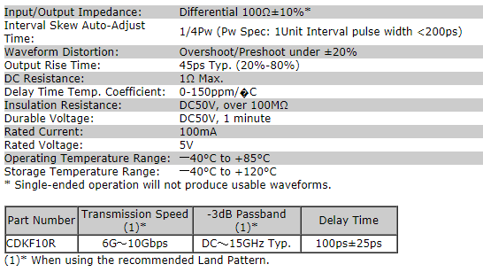
Common Specifications (provisional)
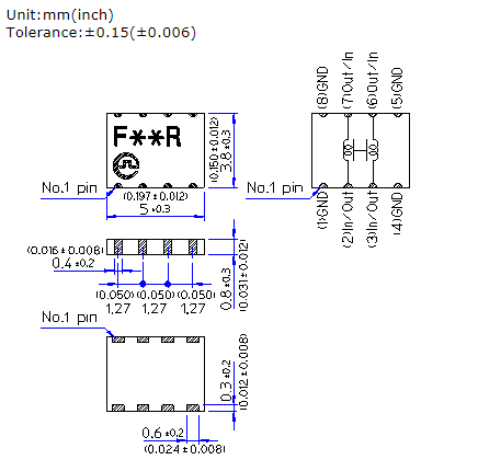
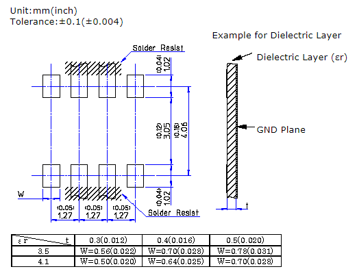
Package Dimensions & Pin Configuration(provisional)
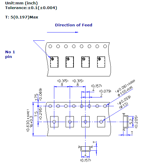
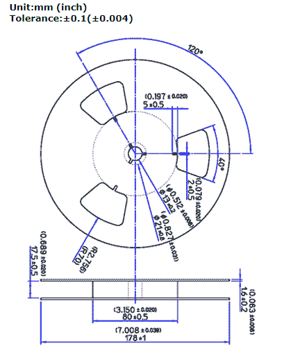
Tape and Reel specifications
In order to accommodate automatic mounting, we provide Tape & Reel packaging. The package is embossed with cover tape and contains 500pcs per reel, as shown below. The reel is marked with supplier name, part number, quantities, and lot number.
DIMENSIONS OF TAPE
Package Dimensions & Pin Configuration(provisional)
Suggested Land Pattern
Suggested Reflow Soldering Conditions

Typical Applications
(1) ECL
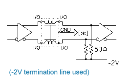
(2) PECL
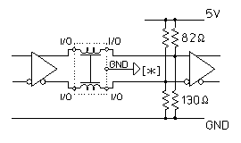
(3) LVPECL
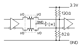
(4) LVDS

Please be sure to connect the GND Termination. (Please See Notes)
Characteristics Examples
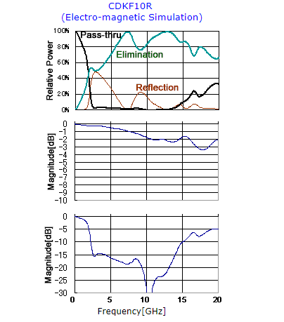
(1)Frequency Characteristics
Top: Elimination of Common Mode Noise, Pass-thru and Reflection Ratio
Middle: Sdd21 Differential Signal Pass-thru Amplitude Characteristics
Bottom: Scc21Common Mode Pass-thru Amplitude Characteristics
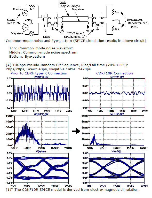
(2)Response waveform of Pseudo-Random Bit Sequence
Technical Note 1: Frequency Characteristics of Common-Mode Impedance
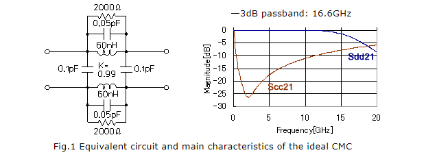
For the CDKF type-R and the ideal common-mode choke coil (hereafter, ideal CMC), the frequency characteristics of common-mode impedance are calculated with a circuit simulator and the difference is verified. The equivalent circuit and the main characteristics of the ideal CMC are shown in Fig. 1. As much as possible, the -3dB passband was made wideband.
The method utilized for calculating common-mode impedance is shown below. In general, common-mode impedance (Zcom) Fig. 2, is generated by a common-mode choke coil from common-mode noise. That value can be calculated from this circuit. Conversely, because the structure of the CDKF type-R absorbs and removes the common-mode noise within the Signal Line-GND circuit, common-mode impedance (Zcom) can be calculated from the circuit arranged and shown in Fig. 3.
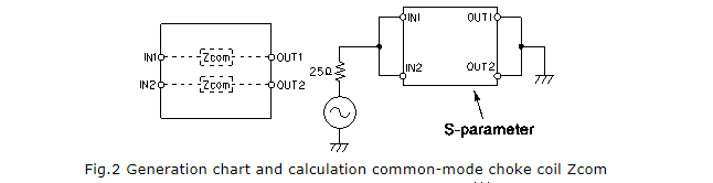
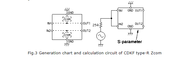
Fig. 4 shows the frequency characteristics of the ideal CMC and CDKF type-R Common-mode impedance from the calculation circuits in Figs. 2 and 3. Here, the ideal CMC uses a circuit simulation S-parameter while the CDKF type-R uses S-parameter derived by the electro-magnetic simulation.
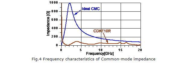
The ideal CMC intercepts the common-mode noise by generating high impedance within the signal line. As shown in Fig. 4, it appears to be effective in the vicinity of 2GHz. However, the inclination of the frequency characteristics is quite steep. Common-mode impedance is reduced as it diverges from 2GHz, and the intercept function decreases. On the other hand, the CDKF type-R is set to the value from the signal-GND circuit corresponding to the common-mode impedance which is constant and small and has a fairly smooth frequency response. There appears to be an advantage to being able to lower the dependency on the frequency and to do a wideband absorptive removal of the common-mode noise.
RoHS Compliance Status
RoHS-compliant
Notes
Always connect the GND terminals. Using this product without connecting the GND could cause deterioration of the common mode noise elimination and delay line functions.
Also, use of only one line will not yield a normal wave form and cannot be used.